The output
Drawings and reports
Generated from the designed model. Finished in the built-in editor. Issued as DXF.
Beam elevation
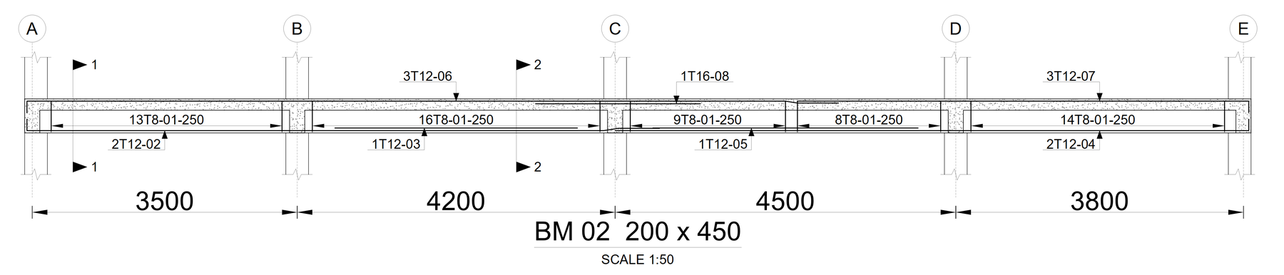 Bar marks along the span, link zones, section marks. 1:50.
Cross-sections
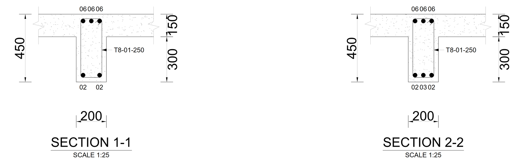 Cut from the same bars as the elevation, slab included. 1:25.
Slab reinforcement layout
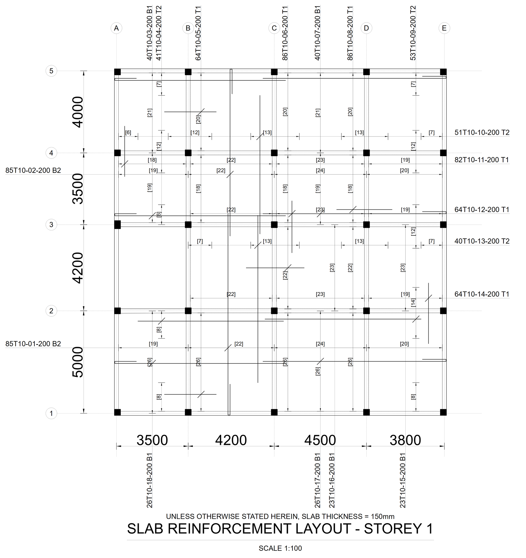 Top and bottom, both directions: mark, count, diameter, spacing. 1:100.
Column elevation
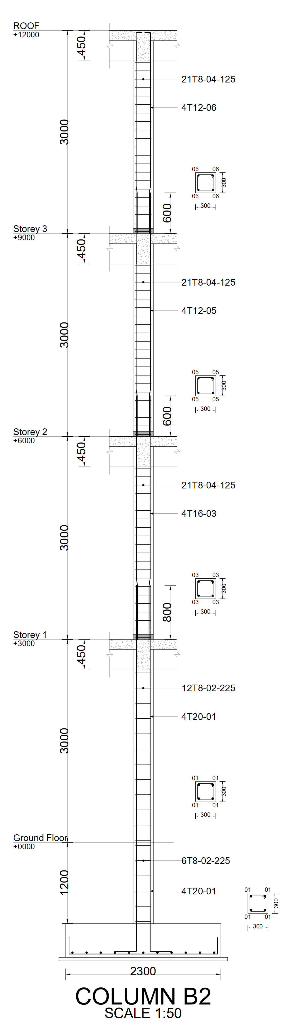 Footing to roof: bars and links per lift, laps dimensioned, a section at every lift.
Pad foundations
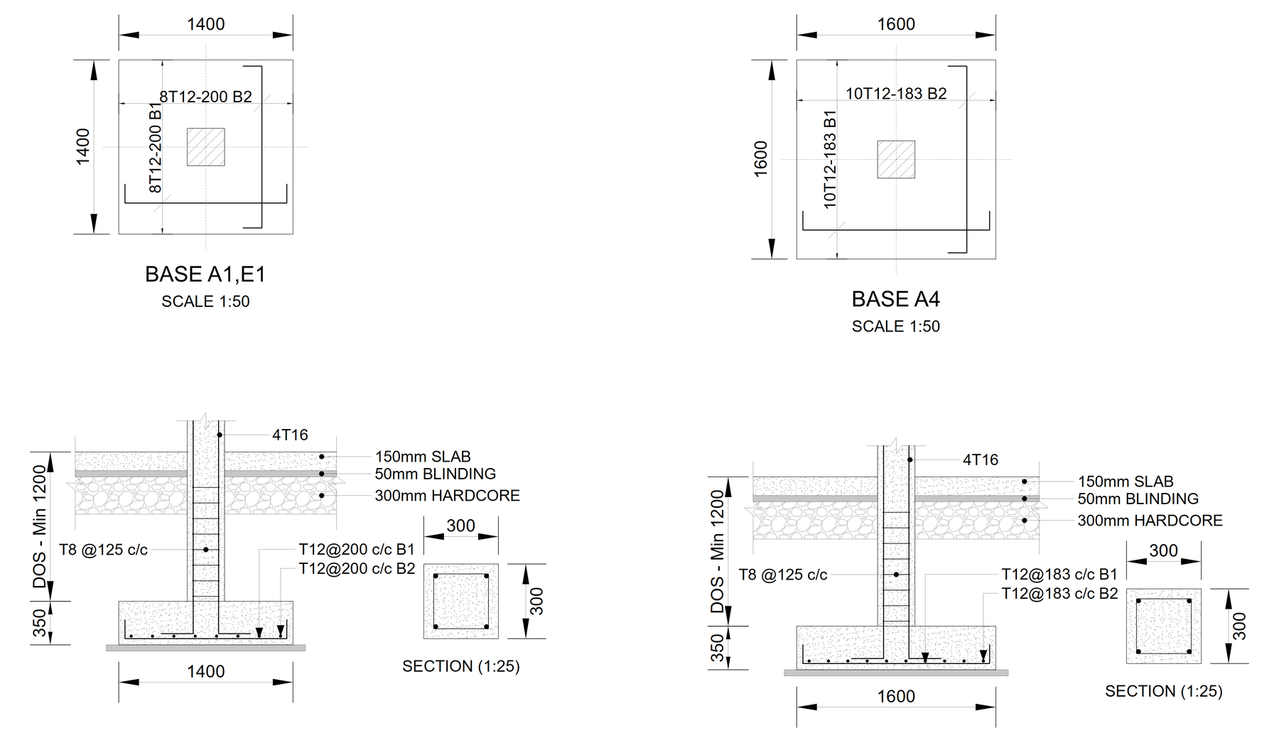 Plan and section per base: mat both ways, column starters, ground-slab make-up.
One set of bars, every view
Drawn, not exported
Elevation, sections and schedule come from the same bars. Change one, all follow.
Finished where you are
Layers, paper space, snaps, dimensions and plotting — inside the program.
Out as DXF
Into your own title block, exactly as the software drew it.
Take a job all the way to the drawings
15 days. The full product. No watermark.